Is bigger really better? Will floating offshore wind work with 15MW turbines and larger?
Floating offshore wind is necessary for accessing some of the best wind resources in the world, which you will find far offshore in deeper water. Another great advantage with floating offshore wind is that it scales well for larger wind turbine generators (WTGs). Larger wind turbines have taller towers and access even better wind at higher altitudes. They can thus expect a higher capacity factor (average production per installed capacity).
Larger wind turbines also result in fewer units to install and maintain at the same installed capacity. This has been a recognised fact stated for years. In its constant search for lower levelized cost of energy (LCOE), the offshore wind community has been pushing each other to go bigger and bigger, and further and further offshore.
In 2007 Equinor installed the Hywind Demo in Norway with a 2.3MW WTG and 82m diameter rotor on a floating spar foundation. The largest wind turbines so far installed on an offshore floater are the 9.5MW and 164m diameter rotors on semisubmersible foundations on the Kincardine project in the UK. The largest WTG that you currently can order for a future project is 15MW with 236m diameter rotor, and there are plans for further upscaling, probably beyond 20MW. How far will this go and what kind of challenges can we expect to meet?

Going bigger
Obviously, a bigger WTG has a heavier nacelle (the house covering the generating components), larger blades and higher tower, and will therefore need a larger floating foundation in order to float and move within the tolerances of the WTG. Larger WTGs and larger foundations give larger forces from the winds and waves, which will need to be taken into account when designing and dimensioning the structure.
To fully understand these forces is a complex task and requires thorough analyses and simulations in advanced computer simulation programs as well as running model tests in wave tanks to validate the input data. Structural analyses need to be run to verify that the foundation and tower can resist the forces. This is an iterative process where the tower and structure may need to be re-inforced in steps. Reinforcement means additional material, additional weight and will, depending on the overall floater concept, require more buoyancy. More buoyancy changes the shape of the foundation which again changes the hydrodynamic forces. Back to the drawing board, start again with simulations and sometimes even another model test in the wave tank…
As you see, this is a highly iterative process with no guarantees for the final result. You don’t know that it will work until you have done the full circle and matured your design to a high level of detail. The further away we are from something that has been done before (e.g. WTG sizes or weather conditions), the more challenging this process is. You can read more about how to assess the maturity of a floating wind design in this recent WindTalks article.
Verifying a floating foundation design for a certain environmental design basis requires both the foundation designer and the wind turbine manufacturer to run detailed integrated simulations and analyses of both the foundation and the wind turbine. The full cycle process can easily take a year to complete. If you are lucky (and/or competent!) they both conclude that the foundation and mooring system will work with the WTG, and the WTG and tower will work with the foundation and mooring system. Hopefully, the final design is something that is possible to construct and install on the final location within the limitations of yards, transport, cranes and installation vessels.
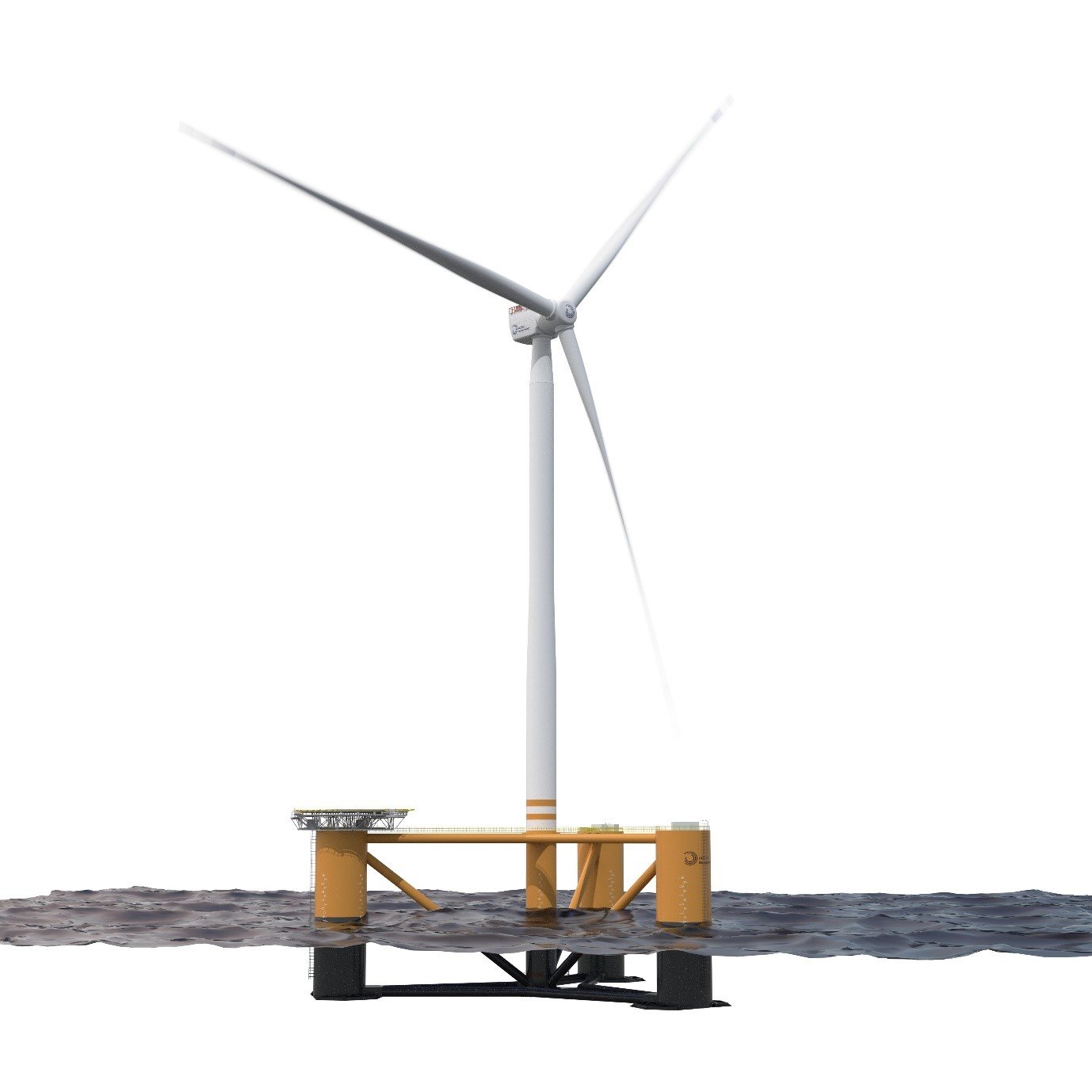
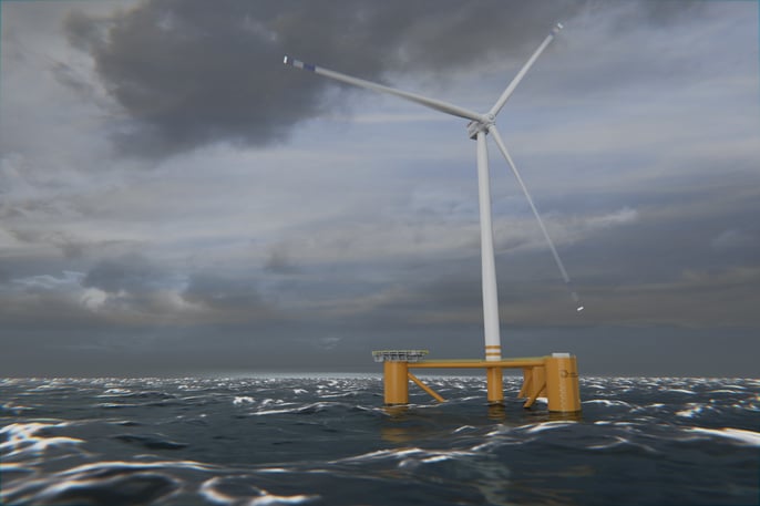
Odfjell Oceanwind's Deepsea StarTM for 15MW WTG. Read more about it here
More challenges to come...
But there are more challenges: The tower for a conventional wind turbine is in principle a steel pipe that is optimised to withstand the loads induced from the winds working on the WTG and the tower, and from the wind, waves and currents working on the foundation and its mooring system. The tower is very much a fatigue driven design which complicates the dimensioning further.
When going bigger you are also faced with challenges related to changes in the structural natural frequencies and the load frequencies. If any of the structural natural frequencies of the floater and tower get too close to the frequency of any dynamic load, the whole structure might “vibrate to pieces”, which is of course not a good thing! Here it is important to understand what we mean with a dynamic load; it is simply a load which is not constant, a load that varies with a certain frequency. For example, due the very existence of the tower and the fact that the wind cannot flow through it, the wind field in front of the tower will be reduced. Every time one of the rotor blades passes in front of the tower, it experiences a small reduction in the load on that blade for a very short moment. This variation in loads on each of the rotor blades will be carried through the rotor hub, via the nacelle and into the tower. For a conventional, three-bladed turbine this happens three times per revolution and the time period between each of these passes is therefore called 3P. Similarly, the 1P is referring to the time it takes for one particular blade to make a full revolution.
To minimize the cost, weight and material use in the generator and rotor blades, the rotational speed is maximised within physical limits set mostly by centrifugal forces and by erosion of the blades leading edges due to collision with rain droplets, hail etc. To avoid damages to the tip of the blades the tip speed is therefore limited to a certain maximum. A larger rotor diameter therefore requires the rotational speed (RPM) to be reduced. Is this a problem? Very much so!
Each of the towers have what we call a structural natural period. This period is simply the time taken by it to undergo one complete cycle of oscillation. The natural period is controlled by mass and stiffness of the tower. A normal tower “eigen period” is often around 3 seconds for a 15MW wind turbine on a floating foundation. Instead of talking about “periods” the engineers most often prefer to measure this as a frequency. Frequency is simply the inverse form of the period T, hence f=1/T. Frequency f is measured in Hz, and in our case the tower natural frequency would be f= 1/3s=0.33Hz. If the RPM of the rotor was, say, 8, the 3P blade passing frequency would be 8/60s*3=0.40Hz.
A tower can, just like a guitar string vibrate in different manners depending on the “mode shape” which is excited. However, in our case we are mainly interested in the “first mode shape” which is the tower bending back and forth about its base. This mode shape has the lowest frequency of all its possible mode shapes of a free-standing tower.

In a fatigue driven design it is of particular importance to keep the natural frequency of the main structural components robustly away from the frequencies of any repeating forces, like regularly occurring waves and the 3P. If the 3P is close to the natural frequency of the tower, the fatigue life of the tower is dramatically reduced. This is called resonance and you have probably seen movies of how structures like bridges can be torn apart in a minute when it happens. Here is a link to one example. In this example it is the torsional mode of the bridge which is triggered by vortexes from the wind passing the bridge. The vortexes are released as a result of the torsional deflection of the bridge itself and the motion becomes coupled, a kind of chicken and egg situation. Combined with lack of any useful damping to stop the motions, as in this famous example, the result can quickly become catastrophic.
Soft-soft, soft-stiff and stiff-stiff towers
The way we have been able to avoid this challenge so far when scaling up floating wind turbines has been to manipulate the natural period of the tower by optimising the geometrics of the tower itself and the floater. A larger diameter tower stiffens the tower. However, there are also limits to how much you can increase the diameter of the tower. A larger tower diameter reduces the clearance between the tower and the blade tip under extreme conditions. If this is the case, the operation of the wind turbine might have to be limited resulting in possible loss in annual energy production. It is also not always straight forward for the wind turbine manufacturer to change the tower diameter to suite a specific (floating) project due to standardised geometries of the tower internals. Finally, an increased, non-optimum, tower diameter may also increase the need for a higher wall thickness to avoid buckling of the tower walls. A smaller wall thickness, on the other hand, softens the tower. You can also vary the wall thickness along the tower.
A “soft-soft” tower has a natural frequency well below the 1P of the turbine. A “soft-stiff” tower lies between the 1P and the 3P. A “stiff-stiff” tower is well above 3P. Wave frequencies typically fall within and below the 1P bracket, which normally eliminates the use of soft-soft towers for floating wind.
The ideal design for floating wind turbines below 12-15MW is a “soft-stiff” tower, however, the challenge when we approach 15MW and above is that the tower is becoming too stiff. In other words, the tower eigen frequency is becoming close to the 3P blade passing frequency. If the loads are too high in one of your design loops as described above you would like to increase the wall thickness “just a little bit”. The problem is that the tower then get even stiffer and you get even closer to the 3P blade passing frequency, hence increasing the fatigue loading even more. See the problem?
One solution is then to “jump to the other side” and go to a “stiff-stiff” tower design. The problem here is that the jump is pretty large. Unfortunately, the structural frequency only changes with the square root of the stiffness. So, the tower would have to be made considerable stiffer, and therefore heavier, in order to jump to a “stiff-stiff” design. Stiffer towers require larger diameter tower and/or significantly larger wall thicknesses, leading to very heavy towers and the vicious circle of growing foundation sizes and weights.

There is however one more trick in the book: It is possible to decrease the tower natural frequency by increasing the rotational inertia of the floater itself. This may seem counter intuitive at first glance, at least for us it did, but can be seen by testing in a suitable simulation software. The best way to understand it is maybe to envisage a free flying tower in “outer space” not connected to anything. Then give it a real blow with Tor’s hammer and see how the tower would vibrate. In this case the tower would vibrate with a higher frequency, and the mode shape would also look different.
The other extreme would be a tower rigidly connected to earth (with a “infinitely” large rotational inertia). Then with our floater attached at one end of the tower we should get something in between, and we do! Point is, the larger the floating platform, the lower structural eigen period of the tower. The problem is again, increasing dimensions of the floater to stay away from the frequency “danger zone” is a costly solution, driving up the overall LCOE.
The "death valley" of WTG sizes
The tower frequency issue for floating wind is particularly challenging when moving to WTG sizes in the range of 16-22MW, as illustrated in the figure below. If you have a foundation that is not optimised for tower fatigue loads the problem might occur even on smaller turbines, including for the next generation 15MW WTGs.
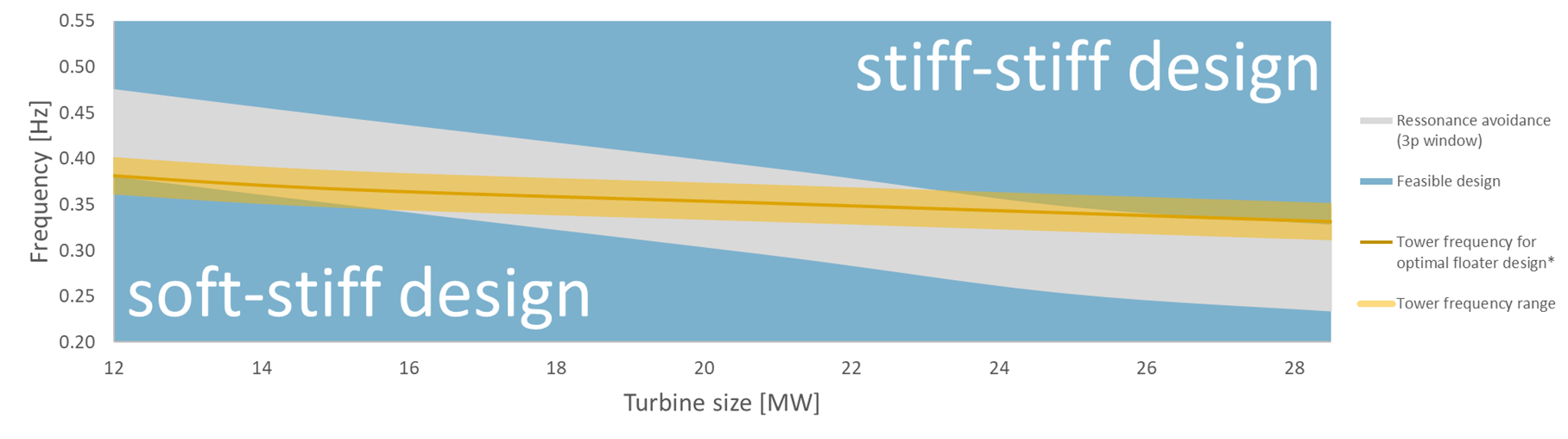
So, is the 3P challenge representing a dead end for floating offshore wind with large turbines? As many times before in history the solution lies in innovation. Odfjell Oceanwind has recently presented its new and innovative HybridTower™ which incorporates a section of fibreglass into the tower or in the floating foundation itself, using the same technology as is used for connecting the wind turbine blades to the nacelle. This allows us to fully control the tower stiffness and avoid the 3P issue all together, still maintaining structural strength to carry the larger WTGs. Hence, both the tower and floater can be optimally designed without having to think about increasing the size to cater for the 3P issues. In this way the tower frequency will always be tuned to be “just perfect” at the end of the design loops.
A study has been done together with Siemens Gamesa and the paper was presented at NTNU / Sintef’s EERA Deepwind conference in Trondheim in January. 
Floating offshore wind is still in its infancy. We have not yet seen the turbine sizes we need to see for the LCOE levels we want to be at. The journey we need to go through will represent new challenges that have never been experienced before. Learnings from other industries like onshore wind and bottom fixed offshore wind is only partly relevant. Other skills and competencies will be required to succeed, to fully understand the challenges, invent the necessary solutions and manage the risks. A whole industry will have to learn and adapt.
Odfjell Oceanwind builds on a legacy that has proven to solve similar challenges before. Odfjell Drilling and Odfjell Technology have for more than 50 years been at the forefront in harsh environment offshore drilling with semisubmersible floaters, pushing the limits to accomplishments we never thought were possible. Odfjell Oceanwind’s vision is to accelerate floating wind. To succeed in doing so we intend to continue pushing the limits and live up to our core values: committed, trustworthy and competent!
The HybridTower™ is patent pending.
--
|
By: Eystein Borgen Eystein is the CTO of Odfjell Oceanwind and co-funder of the company and Sway. He is the inventor of the Sway floating wind turbine system. |
|
|
By: Espen Engebretsen Espen is the VP Global Performance and Digitalisation of Odfjell Oceanwind. He has more than 10 years of experience with design, R&D and coupled Global Performance Analysis of large floating offshore structures and their mooring systems (floating wind specifically since 2018)
|